Connecting components with lines
Hermes network files have a .her extension.
Select File→Load Network to load an existing network. Note that if that network had a map the map file must be in the same directory as the .her file.
Select File→Save network to save a design . Note that you must also type the .her extension.
You can scroll in the area using the cursor keys.
Clicking with the middle mouse button (wheel) anywhere on the map centers on that location.
Keys ‘+’ and ‘-‘ of the numpad zoom in and out. You can also use the mousewheel for zooming.
Drag holding down the right mouse button to pan the network.
The coordinates of the current mouse position are displayed at the bottom left corner.
Pins are small colored circles used to mark a specific point on the map. They don't have any other function related to the network.
Select Pins→Set blue pin and click on the map to place the blue pin e.t.c.
Select City Map→Load Map Picture to load a map of a city. After loading you should adjust the map scaling.
Select City Map→Set Map Scaling to set the map scaling. Measure the size of something on the map using the coordinates displayed down left and compare it to its real size , in order to get a good scaling value.
City Map→show/hide shows/hides the map respectively.
You can design a network by inserting , placing and connecting various network components : stations , capacitors , nodes and crossings.
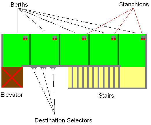
Stations are where people embark on vehicles. In order to go from a place (origin) to another (destination) a person must:
A person will come to a station and insert a bar-code card to a device with a keyboard (destination selector). He will type his destination and if everything is ok he will climb the stairs to go to the most forward berth and insert his card in the corresponding stanchion. If everything is still ok he will embark to the next vehicle that stops in front of him and opens its door. After embarkation he will press the “GO” button inside his vehicle. The door shuts and the trip begins.
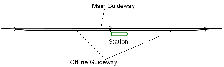
Press ‘S’ and click on the design area to place a station. Station comes attached with entrance/exit ramps + a main guideway segment.
You can move a station along with its corresponding guideways by dragging it.
click on a station to select it. The station will turn red.
To change the orientation of a station , select it and then left click anywhere on the map while holding down the shift key. The station (and its corresponding guideway segments) will be oriented towards the point you clicked.
Capacitors are storage areas for empty vehicles. They provide vehicles when needed and receive any surplus vehicles from nearby stations. They also “absorb” any waveoff vehicles (=a vehicle that tries to enter a station but the station is full - the vehicle continues travelling on the main guideway and goes to the closest capacitor).
There can be many capacitors in a network. In a well designed network each station must be close to a capacitor. You can put quite many capacitors if you want in order to improve network performance. Obviously if you put only a few capacitors they will be large. If you choose more capacitors they will be smaller.
Capacitors don’t have a size : each capacitor can handle an unlimited number of vehicles. However after the simulation ends , simulator will tell you how much capacity was used in each capacitor , giving an estimate in how big each capacitor should be designed in a real system.
Press ‘C’ and click on the design area to place a capacitor.
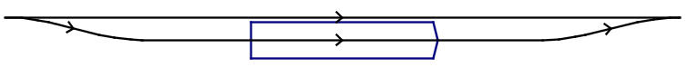
Capacitor also comes attached with entrance/exit ramps + a main guideway segment.
Moving , selecting and turning a capacitor is the same as a station.
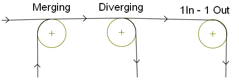
Nodes are guideway intersections.
Press ‘N’ and click on the design area to place a node.
A node does not have an orientation , but it can rotate clockwise or counterclockwise. Selecting a node and clicking anywhere on the area while holding down the shift key will toggle between clockwise and counterclockwise rotation.
Moving and selecting a node is the same as a station.
You can make 2 types of intersections:
You can also use a 1 input→1 output node in order to properly place a line on the design area.
If you need a 2 input→2 output intersection you can make it using 4 nodes , as you can see in the picture.
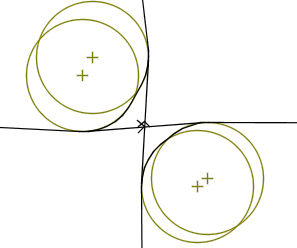
However you can do it more easily by placing a crossing. Crossings are 2-level intersections.
Press ‘1’ and click on the design area to place a crossing.
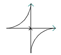
Moving , turning and selecting a crossing is the same as a station.
After placing some network components you can connect them with guideway segments (lines).
Press “L” , click once at the starting and once at the ending network component in order to connect them.
When clicking on network components you must:
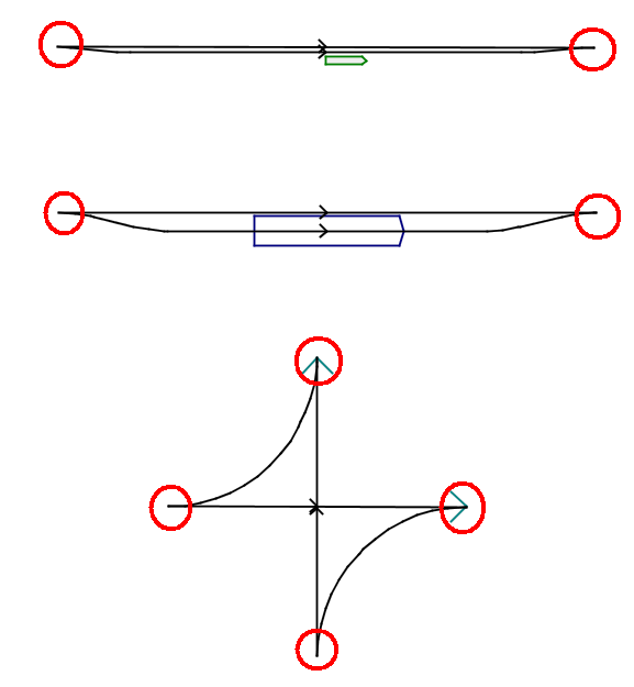
Next figure shows the connectors of each network component (marked with red circles).
Select a network component with attached lines on it and press delete in order to remove any lines attached to it.
Select a network component with no attached lines and press delete in order to remove it.
Select Action→Design Done in order to check for any errors and proceed to runner. Remember to save your design first if you want to keep it.
In a correct design :